The AerospaceNU club at Northeastern recently built a new rocket for testing experimental mechatronic systems and flew it for the first time with no payload. The rocket is 15 cm in diameter, 3.4 m tall, and has a maximum mass of 23 kg. For future flights, the fins should be sized such that added mechanisms have little impact on flight dynamics. Larger fins will diminish the impact of test systems that extend into the airstream, but they may result in undesirable weathercocking at low speeds or unstable oscillations in yaw angle. Low speed behavior is a primary concern because the wind makes up a significant portion of the rocket’s velocity relative to the air and can cause changes in heading. At low speeds the rocket is also low to the ground and therefore a greater risk to spectators. I was responsible for determining the appropriate fin size for the rocket.
Methodology
I used the following methodology to approach this problem:
- Determine the aerodynamic properties of the rocket for small angles of attack
- Construct a dynamics model of the rocket in flight based on the mass distribution, motor thrust curve, and the previously determined aerodynamic properties
- Use the dynamics model to predict heading oscillations for several fin sizes to determine the largest fin size with allowable heading oscillation growth rate.
To determine the aerodynamic properties of the rocket, I constructed a CFD model using Ansys Fluent, starting with a mesh designed to capture the wake of the fins in detail using several bodies of influence.
Then I ran this simulation for a range of small angles of attack and plotted the resulting aerodynamic coefficients, as shown below for the case with 30.5 cm fins
Since these coefficient curves are nearly linear, it is reasonable to use linear interpolation to deterimine coefficients for any angle of attack less than the maximum tested with CFD (10 degrees). Then all the forces and moments can be calculated from the coefficients as follows:
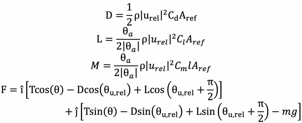
 , where
  is the direction of velocity of the rocket relative to the air,
  .
.
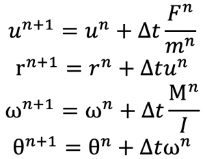
This calculated net force and moment on the rocket can then be used to calculate the rocket pose over time using the following explicit Euler equations and the known moment of inertia and mass of the rocket.
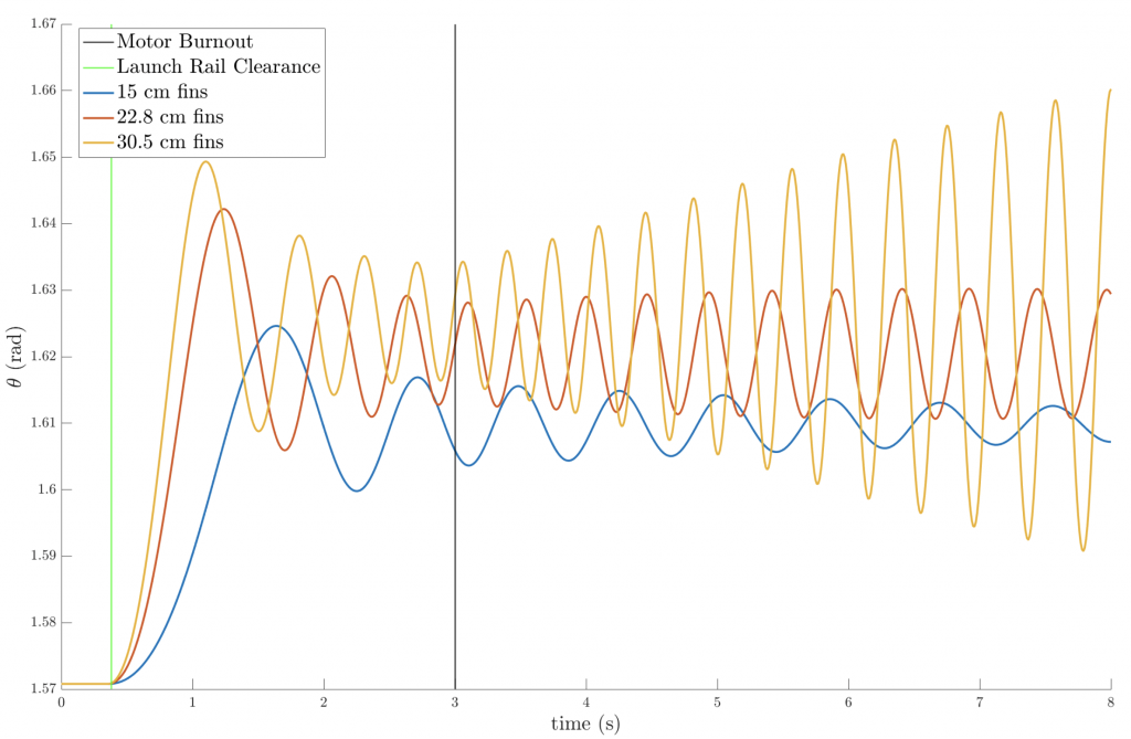
Running my explicit Euler simulation provide the following plot showing the behavior of fins of various sizes
Results and Conclusions
- The 30.5 cm tall fins are likely a poor choice, because they will result in larger oscillations and greater loading on the rocket. The flight is likely not long enough for the oscillations to become large enough to cause the rocket to flip over, but further investigation would be required to determine the point of catastrophic instability. In addition high angular velocities and angles of attack may invalidate the results of these simulations since the underlying CFD assumes steady state.
- The 15 cm tall fins result in continual damping of the oscillations, which is desirable. However, at the beginning of the flight when the center of mass is low in the rocket (from the weight of the propellant), the short fins put the center of pressure within a few centimeters of the center of mass. That means that any small inaccuracies in these calculations or uncounted mass in the bottom of the rocket could result in the rocket flipping over immediately after leaving the launch rail.
- The 22.8 cm tall fins are the best choice for this rocket, because they are roughly as big as they can be made without causing amplified oscillations after burnout. They put the center of pressure well aft of the center of mass throughout the flight and will allow for the addition and subtraction of mass as experimental mechanisms are added or removed from the rocket. Opting for a fin height on the upper end of the stable range will also prevent instability caused by experimental mechanisms that extend into the airstream at the top of the rocket (as will likely be the case for future launches). Given these results from my simulations, we have used 22.8 cm tall fins for the rocket’s first two flights, and we will continue to do so for future launches, including a test flight for an experimental Marman clamp system.
Skills Learned and Applied
- CFD: I learned how to use Ansys Fluent to determine aerodynamic coefficients for a body in flight
- Numerical Modeling: The explicit Euler time-stepping simulation allowed for the incorporation of a range of inputs, including launch rail effects, wind, motor burnout, shifting center of mass, and aerodynamic nonlinearities that would complicate an analytical approach.
- Dynamics: The project involved extensive application of dynamics principles relating forces and moments to acceleration, velocity, and position of a rigid body.