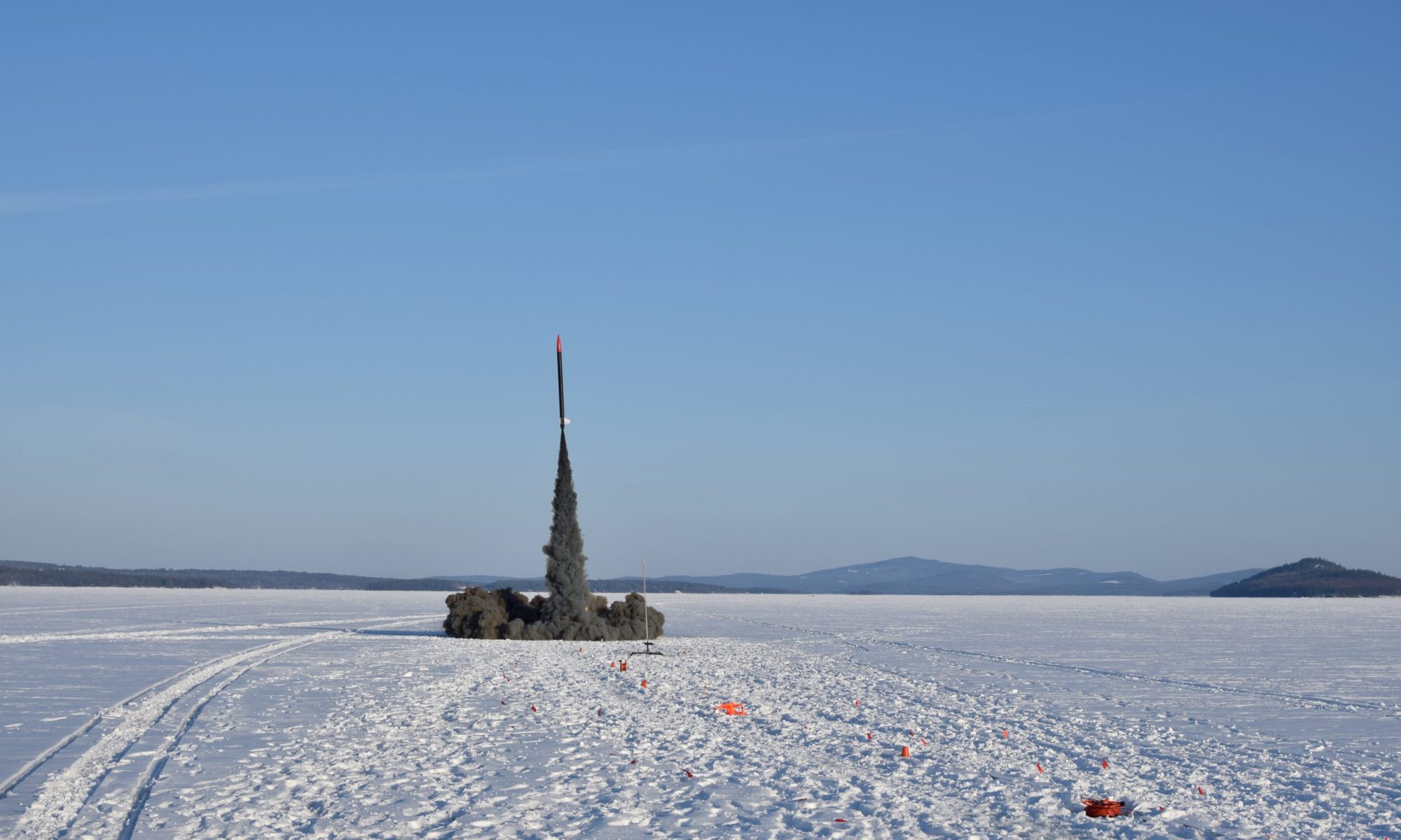
Over the past year I have been working on a test rocket for data collection and validation of novel systems as part of an aerospace club project at Northeastern University. Among other things, I designed the instrumented nose cone assembly that allows for the measurement of airspeed and the axial drag force on the nose cone.
There was a challenging set of requirements for this assembly:
- The fiberglass nose cone shell must be axially supported by a load cell only.
- There should be no screw heads or other features on the curved portion of the outside of the nose cone (to avoid influencing the drag measurements).
- The nose cone must have a pitot tube at the very tip for measuring airspeed.
- The assembly must also incorporate a set of static pressure ports at least one rocket diameter from any transitions.
- The lower end of the apparatus must be a sealed tube to accommodate ejection charges.
- The apparatus must withstand in-flight loading, including off-axis loads.
- It must be possible to assemble and disassemble the apparatus to switch out electronics or other components.
Over the course of several months, I developed a system to fulfill these requirements
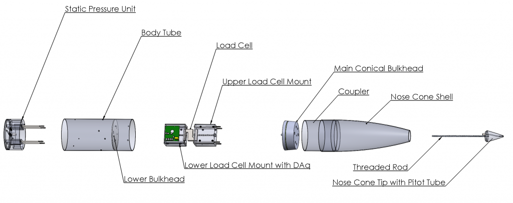
The figure above shows the different parts of the assembly and the process by which they are assembled. First, the nose cone tip with the threaded rod attached is placed on top of the nose cone shell. Next, the main conical bulkhead is inserted into the nose cone, and a nut is tightened onto the bottom of the threaded rod, clamping the bulkhead and the tip in place. Then the load cell unit is screwed into the bottom of the main conical bulkhead (there are captive nuts on the upper surface), and the static pressure unit is placed against the lower bulkhead. Screws run through the static pressure unit and the lower bulkhead and into the load cell mount to hold the assembly all together. Everything can be disassembled except the lower bulkhead, which is held in the body tube with epoxy.
With this assembly, the nose cone is supported axially by the load cell and radially by the coupler tube attached to the bottom of the nose cone. The coupler tube extends down into the body tube, but it can slide axially as the load cell compresses (there is a small gap between the bottom of the nose cone shell and the top of the body tube).
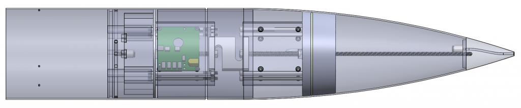
The PCB shown is the data acquisition board for reading pressure data off the static pressure port transducer and the transducer attached to the pitot tube. These readings are compared to determine airspeed. The PCB also has a load cell amp on it to read the axial force on the nose cone from the load cell.
Once fully assembled, the apparatus is attached to the top of the rocket.
To date, the assembly has been flown three times and provided valuable data to the simulations team. The avionics team continues work to improve data collection electronics, and a launch is scheduled for October 16.